Jump to a question in this guide
- What are a snowblower’s three separate jobs?
- How do I find the right instructions for my machine?
- How do the auger and impeller get snow into the chute?
- What do the chute and the hinged hood each change?
- Is it an electric starter or a battery-powered machine?
- Why are the travel and snow-drive controls separate?
- Why does wet or heavy snow change how it performs?
- What are skid shoes and the scraper—and where are they?
- What needs to be planned around the path and receiving area?
- What if it hits something, vibrates or sounds different?
- Why is “it has stopped” not permission to reach inside?
- What changes after storage, freezing weather or charging?
- What can I tell a service provider without testing the fault?
- When does repair, replacement or hiring a service make sense?
- Why can one working function fool you about the rest?
- What should the next person using it understand?
- The front auger gathers snow, the impeller throws it and traction moves the machine. One working function does not prove that all three are working.
- Skid shoes support the front housing; the long scraper is its lower collection edge. They are different parts with different wear and service questions.
- An electric starter helps start a fuel engine. A battery snowblower uses packs and an electric drive, with a separate charging task.
- Never put hands or feet in the intake or chute, even when it looks stopped. Use the actual manual and appropriate service arrangements; never start a fuelled machine in a garage or shed.
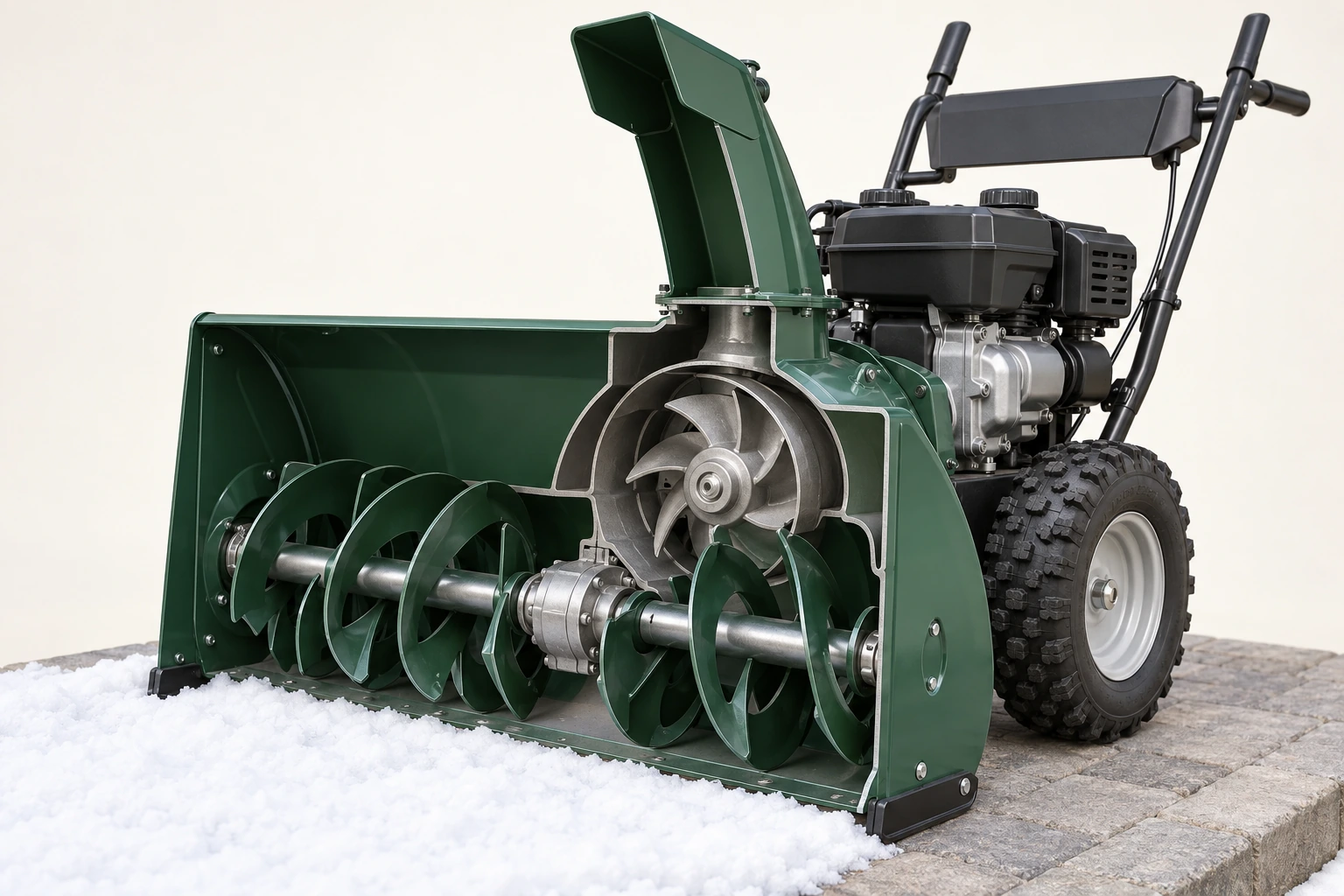
The front auger gathers snow toward the middle, while a separate impeller sends it into the chute. The wheels move the machine; turning wheels do not establish that snow is moving through the throwing route.
About this illustration
Conceptual two-stage arrangement; exact internal geometry, speed, guards, clearances and actual operating condition are not established. No access or clearing instruction.
10 picture lessons appear beside the questions in this guide. Use them to understand the explanation, then consider what it means for your home.
What are a snowblower’s three separate jobs?
A two-stage snowblower gathers snow, throws it through a chute and moves the machine along the ground. Its front auger is a spiral gathering part. A separate impeller behind the middle accelerates the collected snow into the discharge route. Wheels provide travel. Understanding those jobs separately helps explain why a machine can still move forward while producing little snow discharge, or throw snow while its travel function needs attention.
That distinction matters when a winter morning goes wrong. “It starts” tells you about starting. “It moves” tells you about travel. Neither tells you that the snow-handling parts or chute are doing their jobs. Knowing the parts helps you describe a change without buying a belt, battery or complete replacement on a guess.
Start with the whole-machine illustration. Follow snow into the wide front opening, inward along the spiral auger, through the central transfer area and up the discharge chute. Then look at the wheels separately. The illustrated cutaway makes those hidden relationships visible; on the real machine the covers, guards and protective devices stay in place.
Never put a hand or foot into the intake, auger area or chute, even when the machine appears stopped. CCOHS warns that blades can rotate unexpectedly. If operation changes abnormally, stop using the machine, keep people away and follow the complete matching instructions or arrange qualified help. This guide is not a clearing or repair procedure.
The two-stage examples come from named Toro fuelled and battery manuals. Your machine may have a different stage arrangement, drive or set of controls. Use the illustrations to understand the jobs, then use the actual model’s manual to identify how your machine performs them.
What are the separate collection, throwing and travel jobs?
The front auger gathers snow toward the middle, while a separate impeller sends it into the chute. The wheels move the machine; turning wheels do not establish that snow is moving through the throwing route.
Choose a part name to highlight its explanation below.
- Front auger
Opposed spiral sections gather toward the centre.
- Rear impeller
The separate rear throwing component sits behind the middle.
- Chute
The rising discharge route is visible above its housing.
- Wheel and engine
Travel and power remain distinct from the material route.
About this illustration
Conceptual two-stage arrangement; exact internal geometry, speed, guards, clearances and actual operating condition are not established. No access or clearing instruction.
How do I find the right instructions for my machine?
Find the machine’s model and serial identity in its ordinary accessible location, following its identification information. A brand name, advertised width or remembered purchase year may not be enough. Similar-looking machines can have different control linkages, starters, battery requirements and attachments.
Match the manual to the model and serial range rather than choosing the first search result with a familiar picture. On a second-hand machine, ask the seller for the original manual, supplied attachments and service records. A guard or control that differs from the illustrations needs an explanation before you rely on it.
Ask a provider to show you the actual normal stop, travel control, snow-drive control and chute controls. This is especially useful if the previous user always handled the machine. Understanding an unfamiliar lever for the first time during a storm is a poor substitute for a clear handover beforehand.
The retained fuelled manual covers Toro Power Max824OE/826OAE models37798/37799 in its named serial range. The battery manual covers Power Maxe24 model39924. These are historical served editions used to explain parts and mechanisms; they do not establish a current model’s specification or Canadian product approval.
Keep the exact manual link and machine identity together. If the machine has been modified or the correct instructions cannot be found, explain that to the manufacturer or service provider. Do not remove covers, reach into the intake or operate the machine just to get a better identification photograph.
How do the auger and impeller get snow into the chute?
The auger is the wide spiral assembly across the front opening. Its opposing sections gather snow toward the middle. Behind that central area, a different rotating part—the impeller—adds the motion that sends the material into the discharge chute. The wide gathering stage and the throwing stage therefore do different work.
Think of the front opening as the collection area and the chute as the exit. Between them is a transfer route. Snow must be gathered, reach the middle and leave through the discharge path. The picture separates those parts so the word “auger” no longer has to stand in for every hidden part inside the machine.
The power source supplies motion through the machine’s drive arrangements. The named manuals distinguish the auger/impeller drive from traction. Wheel travel can remain while the snow-handling drive has a concern. Equally, a restriction in the snow route or the material being taken in can reduce discharge without proving that a belt has failed.
Describe what happened in ordinary use: did travel continue while discharge weakened, did a change follow an impact, or did the chute stop holding its direction? Those are useful differences for a service provider. A statement such as “the belt is broken” skips over other possibilities unless an assessment has actually found that fault.
Do not restart the machine to reproduce the complaint or look into the intake or chute to see what is turning. The illustrated route teaches the mechanism while the real machine remains guarded. Existing observations and an appropriate service assessment are the useful way to investigate the hidden parts.
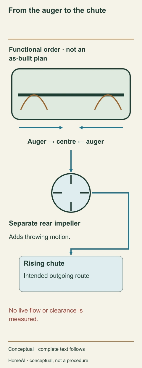
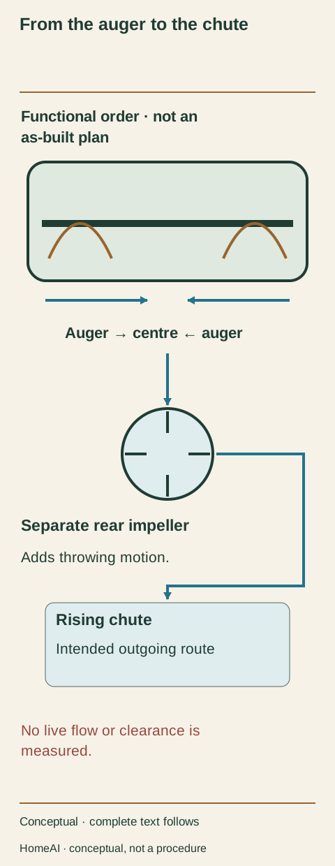
From the auger to the chute
The opposed auger sections feed toward the middle. A separate rear impeller then sends the collected material into the rising chute.
Choose a part name to highlight its explanation below.
- Auger sections
Gather material toward the centre.
- Centre transfer
Connects gathering to the separate throwing region.
- Rear impeller
Adds throwing motion to collected snow.
- Chute
Carries the intended outgoing material.
About this illustration
Conceptual two-stage material route; no motion, speed, internal clearance or actual blockage finding.
From the auger to the chute
The opposed auger sections feed toward the middle. A separate rear impeller then sends the collected material into the rising chute.
- Auger sections
- Gather material toward the centre.
- Centre transfer
- Connects gathering to the separate throwing region.
- Rear impeller
- Adds throwing motion to collected snow.
- Chute
- Carries the intended outgoing material.
Read all the diagram text
- From the auger to the chute
- Functional order · not an
- as-built plan
- Auger → centre ← auger
- Separate rear impeller
- Adds throwing motion.
- Rising chute
- Intended outgoing route
- No live flow or clearance is
- measured.
- Conceptual · complete text follows
- HomeAI · conceptual, not a procedure
What do the chute and the hinged hood each change?
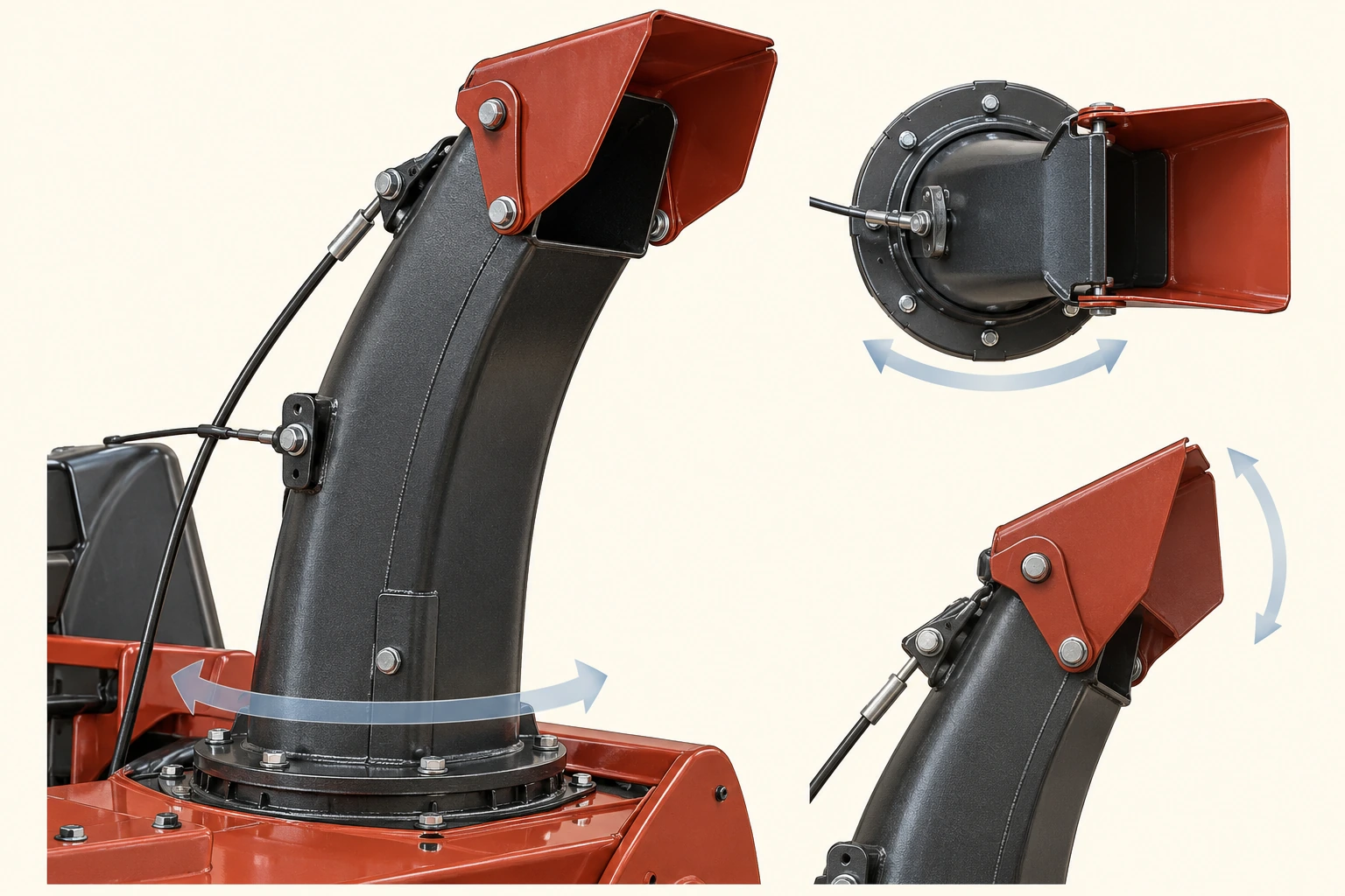
The discharge chute swivels around its base to aim material in a different horizontal direction. The short hood at the top—the deflector—tilts to change the outlet’s elevation. The close-up shows the circular base and the separate upper hinge so you can recognize the two movements on an actual machine.
One joystick may request both movements, but that does not make the two parts interchangeable. A chute that will not turn, a top deflector that will not tilt and an assembly that will not stay where it was aimed are different complaints. In the named Toro arrangement a latch helps hold the selected position.
A changed direction is not only an inconvenience. The outgoing material may include an object hidden in the snow, and a wall or obstruction can redirect it. Plan the receiving area around people, pets, vehicles, windows and other exposures. Do not ask someone to stand near the outlet to judge the stream.
If the aiming assembly will not hold its intended position, stop relying on it and arrange the service described by the manufacturer. Do not hold a chute by hand, force a frozen joint or tie the controls into position. The service request should say which movement or holding function has changed.
The three views explain the joints rather than predict a throwing distance. Distance also depends on the complete machine and material. A pictured chute angle cannot approve a receiving area or substitute for your actual operating instructions.
The swivel chute and hinged deflector aim different ways
The chute swivels at its base to change direction. The hinged deflector changes the outlet’s tilt. If the chute will not hold direction, that is a different concern from weak snow feed at the front. Neither pictured position predicts a throwing distance or a suitable receiving area.
Choose a part name to highlight its explanation below.
- Swivel base
Rotation changes horizontal direction.
- Upper deflector
The hinged hood changes the outlet tilt.
- Separate jobs
Aiming the outlet and feeding snow are different functions.
About this illustration
Original teaching illustration. The actual equipment and its instructions determine the applicable details.
Is it an electric starter or a battery-powered machine?
An electric starter on a fuelled machine helps turn the engine during starting. Once the engine runs, fuel supplies its continuing power. The close-up shows a closed fuel cap, recoil pull handle and electric-start connection as different external parts. A cord used for starting does not mean the machine runs from that cord while clearing snow.
The named fuelled manual says the starter cord is disconnected when the machine is not being started. Use its complete starting and cord instructions for the actual product; the illustration supplies no connection sequence, cord rating or permission to use a damaged lead. An intact-looking cord and a suitable outlet are separate electrical questions.
A battery machine works differently. Its packs store energy for the electric drive. A protective compartment holds them on the machine, and a separate charger replenishes the matching packs. The second picture shows those parts without inventing an engine, fuel tank or owner-accessible wiring system inside the machine.
Pack identity, charger identity and the machine’s instructions belong together. A pack that slides into a similar bay is not automatically suitable. Using the machine outdoors in cold weather is also a different task from charging its batteries; each has its own permitted conditions in the actual manual.
For a fuelled snowblower, never run or even start it in a garage or shed. An open door does not make that a suitable starting place. If a household CO alarm sounds, leave immediately for fresh air and call emergency services from outside. Do not stay inside trying to locate the source.
A starter is not the continuing drive
A fuelled engine can receive electrical starting assistance while fuel supplies continuing motion. The separate battery example supplies its drive from matched packs.
Choose a part name to highlight its explanation below.
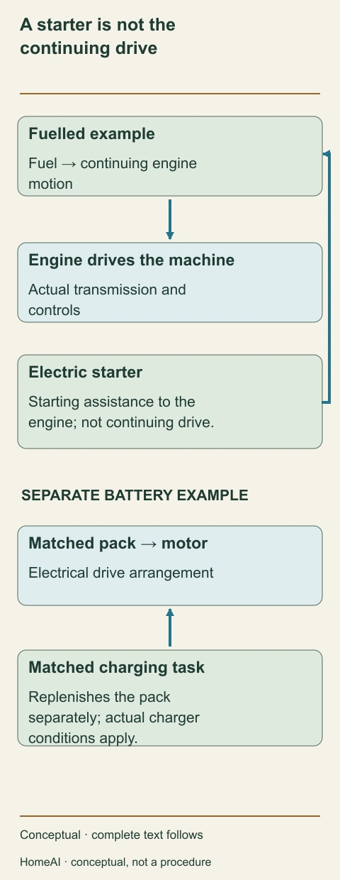
- Fuelled engine
Fuel supplies continuing engine motion.
- Electric starter
Provides starting assistance only in that example.
- Battery drive
Matched packs supply an electric drive system.
- Charging
A separate matched charger and task have their own conditions.
About this illustration
Named Toro architecture comparison; no corded-drive specification, wiring, start or charging procedure.
Electric starting still belongs to a fuel-powered engine
The small electric starter helps turn the fuelled engine during starting; the fuel then powers the running engine. The pull handle and start socket belong to starting equipment. A starting cord does not make this a battery-driven snowblower.
Choose a part name to highlight its explanation below.
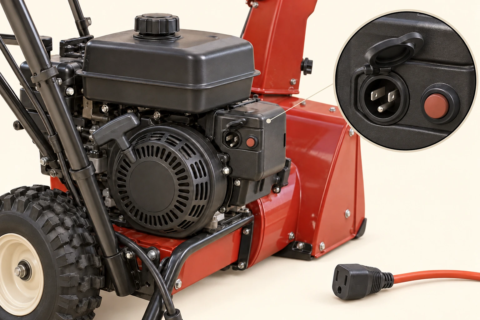
- Fuel tank
Fuel supplies the engine during operation.
- Pull starter
The recoil handle belongs to the starting equipment.
- Electric starter
The start connection assists starting; it is not the continuing snow-drive supply.
About this illustration
Original teaching illustration. The actual equipment and its instructions determine the applicable details.
The battery bay and charger have different jobs
On a battery model, the removable packs supply the machine’s electric drive. The lid covers their compartment, while the separate charger replenishes the matching packs. These pictured parts explain their jobs; use the actual manual for the pack, charger and access arrangements on your machine.
Choose a part name to highlight its explanation below.
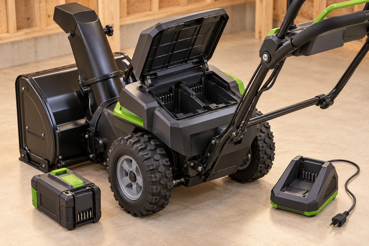
- Battery compartment
The lid covers the intended pack bays.
- Separate pack
The removable pack stores energy for the machine.
- Separate charger
The matching charger replenishes the pack; it is a separate task.
About this illustration
Original teaching illustration. The actual equipment and its instructions determine the applicable details.
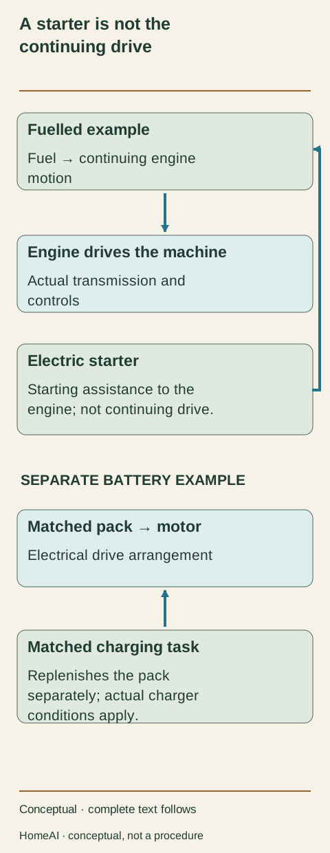
A starter is not the continuing drive
A fuelled engine can receive electrical starting assistance while fuel supplies continuing motion. The separate battery example supplies its drive from matched packs.
- Fuelled engine
- Fuel supplies continuing engine motion.
- Electric starter
- Provides starting assistance only in that example.
- Battery drive
- Matched packs supply an electric drive system.
- Charging
- A separate matched charger and task have their own conditions.
Read all the diagram text
- A starter is not the
- continuing drive
- Fuelled example
- Fuel → continuing engine
- motion
- Engine drives the machine
- Actual transmission and
- controls
- Electric starter
- Starting assistance to the
- engine; not continuing drive.
- SEPARATE BATTERY EXAMPLE
- Matched pack → motor
- Electrical drive arrangement
- Matched charging task
- Replenishes the pack
- separately; actual charger
- conditions apply.
- Conceptual · complete text follows
- HomeAI · conceptual, not a procedure
Starting assistance and continuing drive are different
- Fuelled engine with electric starterStarter assists starting; fuel supplies continuing engine energy Actual engine, starter and matching manual
- Battery and motorMatched packs supply the electric drive; charging is separate Actual machine, packs, charger and conditions
- Another architectureNeeds its own complete route and instructions Do not transfer the two named examples
Named Toro examples; no corded-drive, charging-temperature or starting procedure supplied.
Further reading: Toro · Power Max824OE/826OAE operator manual; Toro · Power Maxe24 60V Snowthrower operator manual; Health Canada · Carbon monoxide: Preventing exposure; Health Canada · Electrical product safety.
Why are the travel and snow-drive controls separate?
Traction is the job of moving the machine over the surface. The auger/impeller drive is the job of moving snow. A speed selector chooses the intended travel setting, while the chute control has its aiming job. The liked handlebar picture brings those control types together without requiring you to guess their functions from a lever’s shape.
Read left and right through the actual manual’s operating-position convention. Do not assume the lever on one side always has the same role on every brand or year. A control that looks like a familiar lawnmower handle may request a different function on a snowblower.
Some controls interact. In the named Toro examples, engaging both drive levers creates a documented interlock: the traction lever can hold the auger/impeller lever engaged. That is why two visible levers are not necessarily independent in every operating state. Obtain the exact explanation for your machine rather than copying another owner’s release sequence.
Unexpected travel or a dangerous function continuing after the control is released needs attention. Stop relying on the machine and arrange qualified service. Do not tie a lever down, defeat a switch or use another person to restrain the machine while you experiment with the controls.
When service is completed, ask the provider to explain the actual control behaviour again. “Cable replaced” names a component task; it does not by itself teach the next user how to stop, travel and control the snow drive. A useful handover joins the repair to the way the complete machine should behave.
Why are travel, snow drive and chute direction different controls?
Separate hand controls let a user request travel, snow collection and chute direction. In the named manual, the two drive levers also have an interlock, so appearance alone does not tell the user how releasing one control affects the other.
Choose a part name to highlight its explanation below.
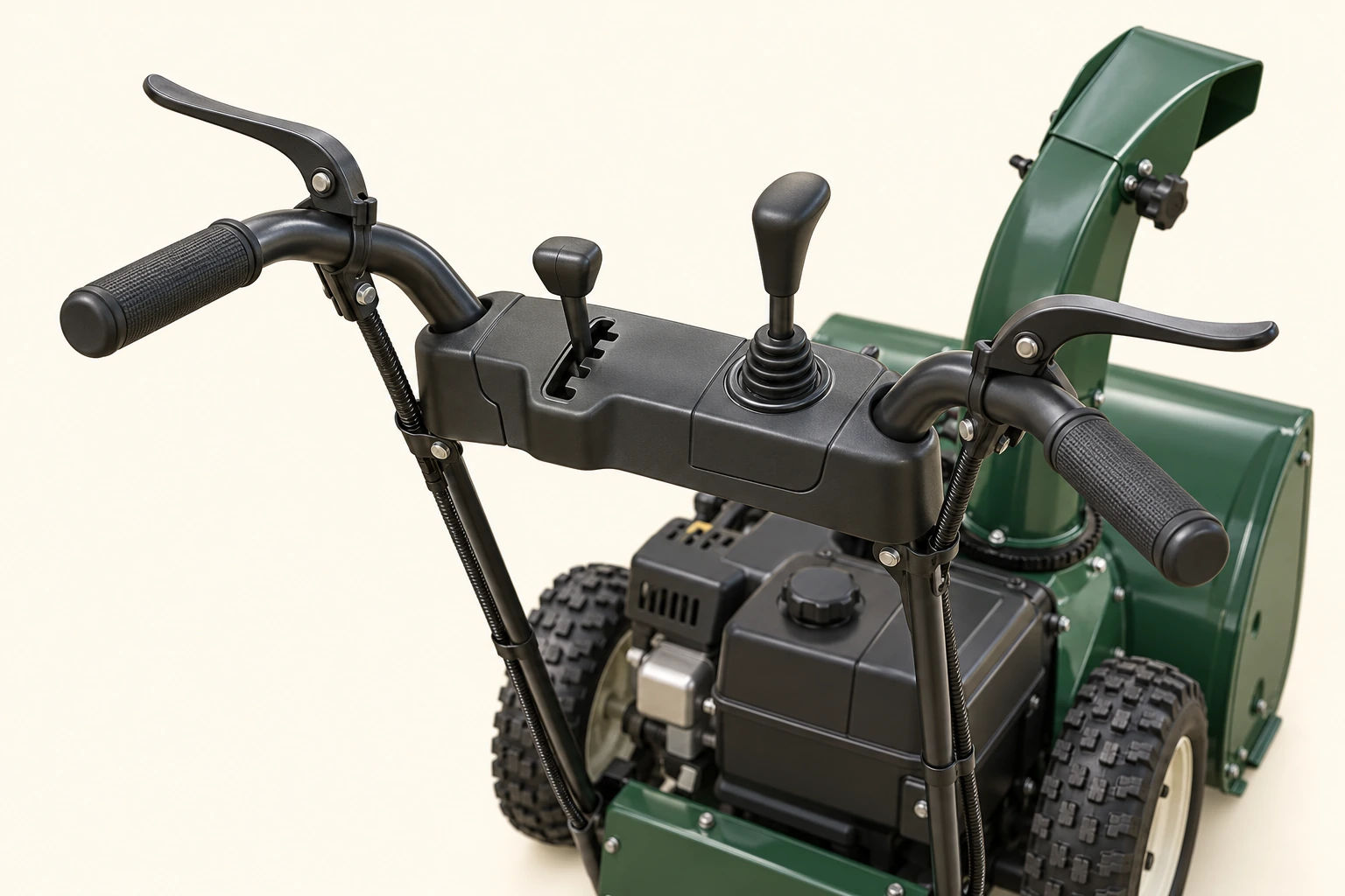
- Handgrip levers
Separate physical controls do not prove independent behaviour in every state.
- Notched selector
A travel-selection concept, not a verified actual setting.
- Chute joystick
A separate direction-control concept.
- Intact sheaths
Covered cables descend without exposing terminations or proving their roles.
About this illustration
Generic intact operator station, not exact control identification, lever side assignment, interlock test or readiness finding. The actual model manual establishes operation and shutdown.
Why does wet or heavy snow change how it performs?
The machine is moving a material, and that material changes. Dry recent snow, wet compacted snow and a dense pile left along an edge are not identical loads. The named manuals include heavy or wet snow, too much material per pass and excessive travel speed among possibilities when discharge is poor.
That gives you context for a complaint, not a diagnosis or a set of operating settings. Describe the conditions already encountered and which job changed. Was there weak discharge, slipping travel, an aiming problem or more than one concern? A provider can then relate the event to the identified machine.
Do not make wet snow the explanation for everything. A strike, unusual vibration or failed control response remains important even if the snow was heavy. Likewise, short battery runtime and a restricted discharge route are different observations; buying more battery capacity does not establish that a mechanical concern has been resolved.
Use the actual product’s operating limits and instructions rather than a generic pass width, gear number or pile-breaking method from this page. If the machine, receiving area or household circumstances cannot manage the task appropriately, use another clearing arrangement. A larger machine cannot repair unsafe footing or create a suitable place for the snow to go.
What are skid shoes and the scraper—and where are they?
The skid shoes are the short supports at the lower outside sides of the front bucket. Their wearing faces meet the surface and help carry the housing. The scraper is the long lower collection edge running between the sides, beneath the auger. In the new front view, you can see all three relationships: shoes at the sides, scraper across the bottom and auger above the ground.
The auger is not intended to be the part resting on the pavement. On the named two-stage examples, the skids and scraper are set together so the auger remains supported above the surface. Tire condition, the housing and the surface also belong in that relationship. Seeing one shoe beside the machine does not tell you the complete arrangement is correct.
The wear close-up shows why a service person looks at the contact faces rather than only the paint. A wearing edge can become thinner or uneven. The named manuals account for wear in their skid and scraper service instructions. Some identified skids can be reversed under those instructions, but that is not a universal instruction to flip any unfamiliar part.
Smooth pavement, uneven paving and loose gravel create different ground questions. A front edge that seems close to a flat sample slab may encounter a raised joint or pick up loose material elsewhere. Ask how the actual machine is intended to meet your surface, including a change from the driveway to a side path.
The pictures supply no clearance, bolt setting or remaining-metal replacement limit. Do not tip a machine, reach underneath or loosen its supports to copy the illustration. Ask the provider to identify the actual parts, their condition and any model-specific adjustment or replacement needed. An impact with a raised edge also needs its own assessment, rather than being dismissed as ordinary shoe wear.
Find the skid shoes and the long scraper edge
The skid shoes are the short supports at the two outer sides. They carry the front housing over the surface. The scraper is the long lower edge between them. Their relationship keeps the auger above the ground; the correct setting depends on this machine and its intended surface.
Choose a part name to highlight its explanation below.
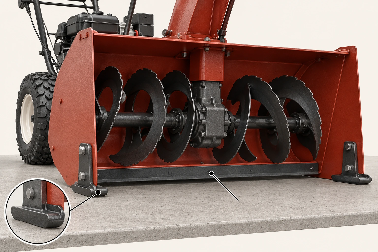
- Side skid shoes
The outer supports meet the surface and support the front housing.
- Scraper
The long lower collection edge lies between the side plates.
- Auger
The spiral gathering assembly remains above and separate from the ground.
About this illustration
Original teaching illustration. The actual equipment and its instructions determine the applicable details.
Wear changes the skid shoe’s supporting surface
A skid’s wearing face is the part that meets the surface. Uneven or excessive wear can change how the housing is supported. The named manuals allow for wear in their service instructions; this comparison gives no replacement thickness or permission to flip or adjust an unfamiliar part yourself.
Choose a part name to highlight its explanation below.
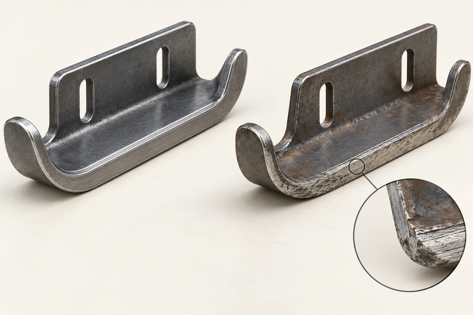
- Wearing face
The lower surface meets the ground.
- Uneven abrasion
The changed wearing edge affects the support question.
- Matching part
Use the actual model and service guidance; no wear limit is given here.
About this illustration
Original teaching illustration. The actual equipment and its instructions determine the applicable details.
What needs to be planned around the path and receiving area?
The work area is larger than the intake width. It includes the operator’s footing, the machine’s travel route and the place discharged material may reach. CCOHS stresses visibility, protective equipment and keeping children and other bystanders away. A headlight helps illuminate a scene; it does not make every part of the receiving area visible.
Before the route disappears under snow, identify objects, path edges, changes in level and loose materials that could be picked up. A small branch or toy is not transformed into harmless snow when it enters the machine. The throwing assembly can send foreign material toward people or property.
Consider ordinary household obstacles: a parked vehicle narrowing the turn, a gate, a shared sidewalk, a low window or a drop beside the path. Those conditions can make another clearing method more suitable even if the snowblower itself operates correctly. The machine also does not remove a layer of ice or repair uneven paving.
Check local requirements where discharge or shared access is involved. This page gives no nationwide municipal permission, safe throwing distance or slope approval. A mechanic assesses the stated equipment scope; the property route and receiving area still need their own practical decisions.
Keep a backup clearing option for the storm that arrives before equipment service is finished. The alternative should not depend on using a machine with an unresolved control, impact or guard concern. That is a useful winter plan, rather than a claim that an engine which started once is ready for every route.
What if it hits something, vibrates or sounds different?
A strike or abnormal vibration changes the question from disappointing performance to stopping and assessing the machine. The named manuals require the machine to be stopped after those events and damage addressed before further use. Do not locate a vibration with your hand, remove a guard or run the machine raised off the ground.
Describe what was already observed: where it happened, the object if known, which function changed and whether another symptom appeared. You do not need to make the event happen again. A previous safely obtained recording may supply context, but a better video is not a reason to restart or approach the discharge opening.
Different parts can be involved. A front-edge strike is not automatically only a scraper problem; a changed snow drive is not automatically the traction system. A quiet engine after the event does not assess the auger, impeller, support parts or controls.
Ask the provider to connect the assessment to the event. If the original concern included weak discharge and vibration, a fuel-system service alone does not answer both. The written explanation should distinguish what was found, what was repaired and what remains outside the work.
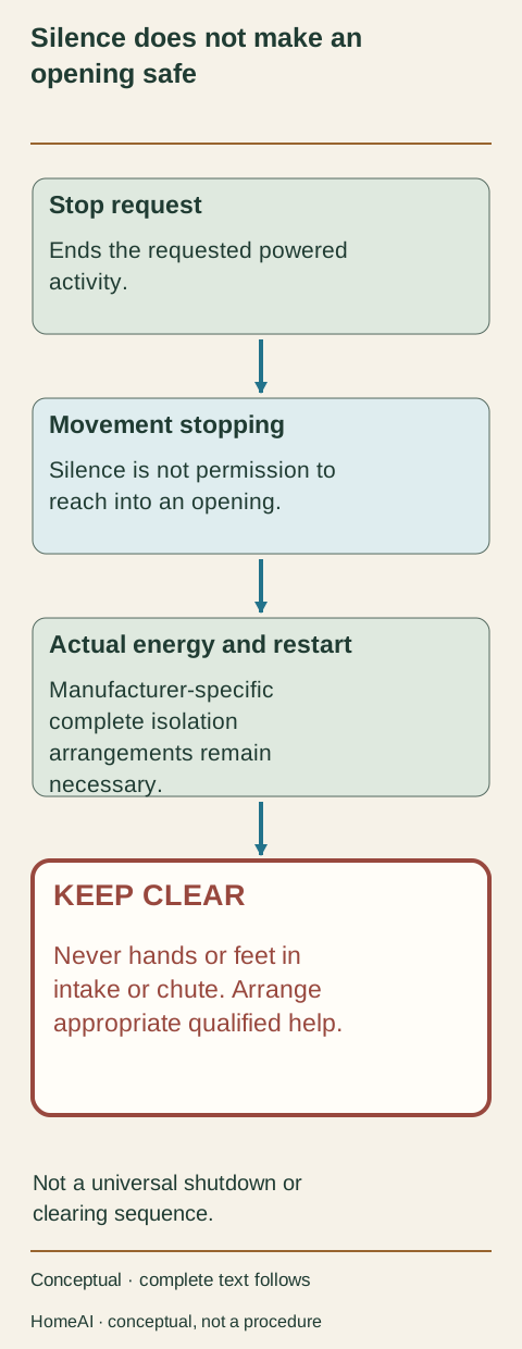
Why is “it has stopped” not permission to reach inside?
Requesting a stop, waiting for movement to finish and preventing an unexpected restart are different jobs. A blocked rotating assembly can still move unexpectedly. That is why a silent engine or motor is not permission to put fingers into the intake or chute.
The stop diagram separates the ideas without pretending that every snowblower has the same isolation sequence. A fuelled engine, starter cord, ignition system, removable battery and start key involve different arrangements. Use the complete instructions for the identified machine and appropriate qualified help when the arrangement is unfamiliar.
Never use hands or feet to clear material from the intake or chute. Keep other people away from the concern. This guide does not reproduce the named manuals’ powered bump-clearing method, tool insertion, cover removal or electrical disconnection steps as a household experiment.
If a provider is arranging service, explain any blocked route and the actual power system beforehand. If you cannot establish how the machine should be handled, keep clear and ask for help. You do not have to complete a hands-on diagnosis before making that call.
The same distinction matters when the machine is left unattended. Know the actual manufacturer’s instructions for stopping, isolation and storage access. A control or key has a particular job; its presence does not replace the full arrangements that keep a child or another user from encountering the machine unexpectedly.
Silence does not make an opening safe
A stop request, movement stopping and prevention of hazardous restart are different concerns. A blocked assembly can still present movement hazards.
Choose a part name to highlight its explanation below.
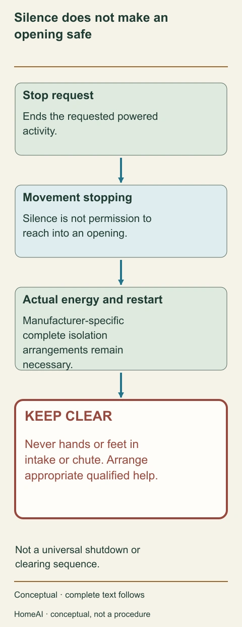
- Stop request
Ends the requested powered activity.
- Movement
Parts need to stop; silence is not access permission.
- Energy and restart
Actual design requires its own complete isolation instructions.
- Keep clear
Never put hands or feet into intake or chute; arrange appropriate help.
About this illustration
Conceptual decision boundary, not a universal isolation, tool-clearing or service sequence.
Silence does not make an opening safe
A stop request, movement stopping and prevention of hazardous restart are different concerns. A blocked assembly can still present movement hazards.
- Stop request
- Ends the requested powered activity.
- Movement
- Parts need to stop; silence is not access permission.
- Energy and restart
- Actual design requires its own complete isolation instructions.
- Keep clear
- Never put hands or feet into intake or chute; arrange appropriate help.
Read all the diagram text
- Silence does not make an
- opening safe
- Stop request
- Ends the requested powered
- activity.
- Movement stopping
- Silence is not permission to
- reach into an opening.
- Actual energy and restart
- Manufacturer-specific
- complete isolation
- arrangements remain
- necessary.
- KEEP CLEAR
- Never hands or feet in
- intake or chute. Arrange
- appropriate qualified help.
- Not a universal shutdown or
- clearing sequence.
- Conceptual · complete text follows
- HomeAI · conceptual, not a procedure
What changes after storage, freezing weather or charging?
A fuelled machine has engine and fuel-system storage requirements. A battery machine has pack, charger and temperature requirements as well as its mechanical parts. Keep the right instructions with the machine; an additive recipe or charge percentage from another product is not a substitute.
The battery model’s use, charging and storage ranges are separate. That is a practical reason to keep the charger instructions, not only the snowblower brochure. A battery suitable for outdoor work under its instructions is not automatically ready to be charged at the same temperature.
If a control has frozen or feels different after storage, do not force it. Explain the condition and ask how the actual instructions apply. This page gives no heating, thawing or powered-running recipe. Never bring a fuelled snowblower into a garage or shed and run it to warm up.
Storage history helps a provider: when it last worked normally, what work was reported and what has changed since. A recent battery purchase cannot assess mechanical controls, and fresh fuel cannot assess a chute latch. Keep those jobs separate rather than treating one new consumable as a complete seasonal service.
Damaged or modified battery equipment needs the manufacturer’s appropriate response. Do not open the pack, improvise a replacement or copy another product’s charging-light meaning. The linked portable-battery guide shows recognizable case, cable and moisture concerns in more detail.
What can I tell a service provider without testing the fault?
Begin with the machine identity, matching manual and what already happened. “The wheels kept moving but the outgoing snow weakened” is useful. “The auger belt must be bad” is a proposed cause unless an assessment has found it. The distinction helps the provider avoid a repair scope built around an assumption.
Mention each concern, including one that happened earlier: a chute that would not hold its position, changed control feel, a strike or an unfamiliar vibration. Do not leave a control problem out because the immediate reason for the call is weak discharge. Those may be separate tasks.
Keep previous invoices in their original wording. Ask what a proposed tune-up actually includes: snow drive, traction, aiming, supports, power system and protective functions as relevant to the complaint. Two providers can use the same general service label for different work.
Accessible identity and an existing account can be enough to arrange the next step. Do not lift a heavy machine, reach underneath, remove a cover or run it for a more impressive photograph. The service provider should determine the appropriate examination arrangements for the actual equipment.
An observation is useful before it becomes a guessed cause
- Wheel travel remains; throw weakensSeparates the reported affected job Does not diagnose a belt or clear the snow route
- Impact or new vibrationChanges safe stop and service scope Do not repeat the event to collect proof
- Completed component workNames a repair task Does not assess every control, route or receiving area
No owner operating test; preserve the qualified report and its actual conditions.
Further reading: Toro · Power Max824OE/826OAE operator manual; Toro · Power Maxe24 60V Snowthrower operator manual.
When does repair, replacement or hiring a service make sense?
Compare options against the same household problem. Repairing a defined drive fault, replacing a machine and hiring a clearing service are different ways to meet the need for usable access. A low repair price tells you little until you know whether the chute, guards, supports or original complaint are included.
Ask for current prices and the actual scope rather than using a universal repair percentage or age cutoff. Age gives context; it does not identify the fault. A mechanically repairable machine may still be awkward for the household’s storage, route or physical needs.
A new machine also cannot repair a raised driveway joint or create a safe receiving area beside a narrow path. Consider equipment and site together. If only one part of the property suits the machine, another clearing arrangement may be needed for the rest.
Keep the chosen option and unresolved work easy for the next user to understand. “Awaiting chute-control service; use the clearing contractor meanwhile” is more useful than “ready for winter” with no explanation. No one should have to reconstruct a purchase conversation before knowing whether the machine is available to use.
Why can one working function fool you about the rest?
Consider a simple example: the machine moves along the driveway, but discharge weakens in wet snow. Continued travel tells you that a travel function was available during that event. It does not tell you the condition of the separate throwing drive or the snow route.
Now add another observation: the chute had previously failed to hold its selected direction. Wet snow may be relevant to the discharge complaint, but it does not explain away the separate aiming concern. Both should be included when arranging service rather than hidden inside a single guess about a belt.
The same reasoning applies to an electric model. A charged pack, an illuminated display and wheel travel do not jointly prove that every mechanical function is working. Ask about the job that changed and how the proposed work addresses it. Do not recreate the event to see which part fails next.
This is an illustrative comparison, not a completed household inspection or an invented repair result. It helps you name the functions and ask a better question. The actual findings and return-to-use arrangements must come from the real machine, its instructions and the appropriate assessment.
What should the next person using it understand?
They should be able to point out the front auger, the throwing impeller’s location, the chute and deflector, the travel controls and the power system. They should recognize the skid shoes and scraper rather than hearing those names for the first time on an invoice.
They should know whether “electric” refers to starting a fuel engine or running a battery machine. They need the actual stopping and isolation instructions, the normal control interaction and the service contact. The illustrations make the parts familiar; the matching manual supplies the specific operating instructions.
Keep a short practical set together: model and serial identity, manual link, completed and pending work, storage instructions and the household’s intended route. A person taking over should not mistake an old invoice for current advice or assume an unresolved concern disappeared because the machine sat unused.
Before the next storm, resolve unfamiliar controls, missing guards, impact concerns or abnormal movement with the right instruction or service. Keep children and bystanders away, never reach into the snow route, and never start a fuelled machine in a garage or shed. The useful outcome is understanding the machine well enough to use its actual instructions and recognize when to stop.
Keep learning about the connected parts
- Walk-behind lawnmowers: understand the deck, cutting, controls and collection
- Portable lithium-ion batteries: connect charging, storage and response
- Carbon monoxide and gas: what to do, and how prevention works
- Driveways and paths: understand the surface before buying
- Build a home-care record that the next person can understand
Canadian context and authorities · Visual atlas · Learning labs
Know the parts.
Know what the words mean.
- Snowblower auger
- The spiral gathering component that feeds snow toward the next part of the designed material route.
- Snowblower impeller
- A separate throwing component behind the auger in the conceptual two-stage arrangement.
- Two-stage snowblower
- An arrangement with a gathering auger and separate throwing impeller; the actual model establishes construction.
- Chute deflector
- The outlet component that changes discharge elevation, distinct from rotating the chute horizontally.
- Traction drive
- The function that moves the machine along the ground, separate from the snow-handling drive.
- Control interlock
- A designed relationship between control functions; behaviour must be learned from the actual model.
- Electric starter
- Starting equipment that helps turn a fuelled engine; it is not the continuing energy source during clearing.
- Snowblower skid
- A support component relating the front housing to the ground on the identified design.
- Snowblower scraper
- The lower collection-edge component in the named examples; condition and setting are model-specific.
- Service isolation
- The actual product’s arrangements for preventing hazardous energization or movement during defined work, not merely a silent engine.
- Auger
- The front spiral assembly that gathers snow toward the centre in the illustrated two-stage arrangement.
- Impeller
- The separate throwing part behind the central transfer area.
- Traction
- The job of moving the machine along the surface.
- Chute
- The discharge passage that swivels to change horizontal direction.
- Deflector
- The hinged hood at the chute outlet that changes its tilt.
- Skid shoe
- A short support at the side of the front housing, with a wearing surface that meets the ground.
- Scraper
- The long lower collection edge between the front housing sides, separate from the auger.
- Battery compartment
- The machine’s protected place for the intended removable packs.
- Interlock
- A documented relationship between controls, so their functions are not always independent.
Questions to bring
to the conversation.
- Which machine, power source and matching manual do you have?
- Can you name the gathering, throwing, travel and aiming parts separately?
- Are the actual surface, receiving area and household route suitable for the machine?
- What changed, what work addresses it, and who will explain the machine before it returns to use?
Separate a showing observation, an existing record and a new professional assessment. Unknown means a question remains; it does not automatically mean a defect.
Use the evidence planner ↗Go to the source.
Original HomeAI explanation informed by these public references. Sources support the underlying guidance; they have not reviewed or endorsed HomeAI. Diagrams are conceptual, and calculator outputs depend on your inputs.
The named fuel and battery manuals explain different machine architectures. Match the actual model before operating, charging, clearing or servicing; the illustrations are recognition lessons rather than a universal procedure.
Publication & source review
First published .
Sources reviewed .
Have a question about your home?
Start with the symptom, timing and what you have observed.
Ask HomeAI